Description
![]()
![]()
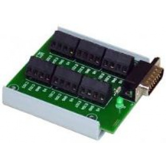
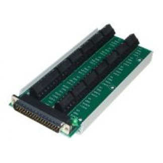
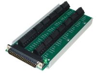
The CB37 terminal board connects to the DB37 connector on the LabJack U6, UE9, or T7, and provides convenient screw terminal access. The CB37 is designed to connect directly to the LabJack (see image below), but can also connect via a 37-line 1:1 male-female cable (not included). Since the CB37 V2.1 has screw-terminals with the same IO/IO/GND/VS arrangement as the U6/UE9/T7 itself, it is compatible with LJTick signal conditioning modules.
The green LED on the CB37 is directly powered by the 5-volt supply (Vs) from the LabJack, so it should be lit whenever the CB37 is connected to a powered LabJack.
The CB37 PCB is mounted to a piece of Snaptrack. The Snaptrack is DIN rail mountable using TE Connectivity part #TKAD (not included).
On older CB37 boards, PIN2 was labeled TX0, and PIN20 was labeled RX0.
On the U6/T7, PIN2 and PIN20 are current sources. On the UE9, PIN2 and PIN20 are UART connections.
The table below shows the pinout of the DB37 connector on the LabJack. Pins 1, 8, 10, 19, and 30, are all connected to GND on the LabJack. On the CB37, all GND terminals connect to a single ground plane and this ground plane is connected to pins 1, 8, 10, and 19, of the DB37 connector. The AGND terminal is simply connected to pin 30 of the DB37 connector. That means the GND and AGND terminals connect to the same single ground plane on the LabJack, but they have different paths to get there.
Table 1. DB37 Pinout
| Pin # | Pin Name | Pin # | Pin Name | Pin # | Pin Name | ||
| 1 | GND | 14 | AIN9 | 27 | Vs | ||
| 2 | PIN2 (200μA) | 15 | AIN7 | 28 | Vm+ | ||
| 3 | FIO6 | 16 | AIN5 | 29 | DAC1 | ||
| 4 | FIO4 | 17 | AIN3 | 30 | GND | ||
| 5 | FIO2 | 18 | AIN1 | 31 | AIN12 | ||
| 6 | FIO0 | 19 | GND | 32 | AIN10 | ||
| 7 | MIO1/CIO1 | 20 | PIN20 (10μA) | 33 | AIN8 | ||
| 8 | GND | 21 | FIO7 | 34 | AIN6 | ||
| 9 | Vm- | 22 | FIO5 | 35 | AIN4 | ||
| 10 | GND | 23 | FIO3 | 36 | AIN2 | ||
| 11 | DAC0 | 24 | FIO1 | 37 | AIN0 | ||
| 12 | AIN13 | 25 | MIO0/CIO0 | ||||
| 13 | AIN11 | 26 | MIO2/CIO2 |